
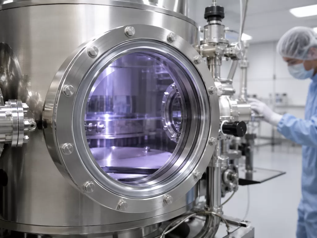
Large sapphire windows provide optical access to vacuum chambers while separating the internal low-pressure environment from the surrounding atmosphere.
They may be used in:
- Équipement de traitement des semi-conducteurs
- Plasma and coating chambers
- Vacuum furnaces
- Laser-processing systems
- Space-simulation chambers
- Scientific instruments
- Optical inspection equipment
- High-temperature or chemically aggressive systems
Sapphire combines optical transmission with high stiffness, hardness, wear resistance, chemical resistance and plasma resistance. However, these properties do not mean that a large sapphire window can simply be made thicker and clamped into a metal flange.
A reliable vacuum viewport must be designed as a complete assembly that includes:
- The sapphire window
- The unsupported clear aperture
- The mounting flange
- The supporting surfaces
- The sealing element
- The clamp ring
- The bolt pattern
- The operating temperature
- The required optical performance
- The specified leak rate
NASA research into sapphire windows has shown that surface condition, mounting geometry, thermal isolation and stress concentration can strongly affect window reliability. A mounting method suitable for ordinary glass is not automatically suitable for sapphire.
Why Large Vacuum Windows Are More Difficult to Design
When the inside of a chamber is evacuated while the outside remains at atmospheric pressure, the window experiences a pressure differential across its entire exposed area.
Increasing the window diameter produces two simultaneous problems:
- The total force acting on the window increases.
- The distance between the supported edge and the center increases.
As a result, window deflection and bending stress rise rapidly as the unsupported aperture becomes larger.
A small increase in diameter can therefore require a significant change in:
- Sapphire thickness
- Support width
- Edge geometry
- Flange stiffness
- Clamp design
- Optical tolerances
- Verification testing
This is why buyers should not specify only the outside diameter and thickness.
The most important mechanical dimension is often the unsupported clear aperture, which may be considerably smaller than the finished outside diameter.
What Counts as a Large Sapphire Window?
There is no universal diameter at which a sapphire window becomes “large.”
The engineering difficulty depends on the relationship between:
- Unsupported aperture
- Finished thickness
- Pressure differential
- Mounting condition
- Window shape
- Sapphire orientation
- Surface condition
- Température
- Required safety margin
- Optical deflection limit
A 100 mm window may be relatively straightforward when it has a small unsupported opening and a wide support area. The same outside diameter may be much more difficult if almost the entire surface is exposed to the vacuum.
Rectangular windows can also be more demanding than circular windows because stress distribution depends on aspect ratio, corner geometry and support conditions.
Pressure Differential Across a Vacuum Window
The RFQ should identify the maximum pressure on both sides of the window.
Do not state only:
Operating condition: vacuum.
Instead provide:
- Minimum chamber pressure
- Maximum external pressure
- Pressure during pump-down
- Pressure during venting
- Possible reverse pressure
- Proof-test pressure
- Pressure cycling frequency
- Emergency or fault conditions
For most chambers operating near vacuum with ambient air outside, the design pressure differential is approximately one atmosphere. However, the assembly should also be reviewed for transient and abnormal conditions.
En voici quelques exemples :
- Rapid pump-down
- Rapid venting
- Gas backfill
- Chamber overpressure
- Local pressure pulses
- Accidental external pressurization
- Differential pressure during leak testing
The pressure direction should be shown on the engineering drawing.
Understanding Window Deflection
Deflection is the movement of the sapphire window under pressure.
For a circular plate under a uniform pressure load, deflection is influenced by:
- Pressure differential
- Unsupported radius
- Window thickness
- Elastic modulus
- Poisson’s ratio
- Edge support condition
- Residual mounting stress
The most important practical relationship is that deflection increases very rapidly with aperture size and decreases strongly as thickness increases.
However, increasing thickness is not always the most efficient solution.
A thicker sapphire window may introduce:
- Higher material and machining cost
- Longer manufacturing lead time
- Greater optical path length
- More birefringence-related effects
- Greater absorption in some wavelength ranges
- Higher assembly mass
- Increased thermal gradients
- Greater difficulty controlling flatness and parallelism
The design should therefore balance mechanical strength, optical performance, manufacturing feasibility and system cost.
Deflection Is Not the Same as Failure
A sapphire window may remain mechanically intact while deflecting enough to interfere with the optical system.
Possible effects include:
- Transmitted wavefront distortion
- Focus shift
- Image distortion
- Beam steering
- Changed optical path length
- Misalignment with internal components
- Contact with nearby hardware
- Uneven coating stress
- Seal movement
For an observation viewport, moderate elastic deflection may be acceptable.
For an interferometer, laser system, imaging system or precision optical measurement chamber, the allowable deflection may be much smaller than the mechanical failure limit.
The RFQ should therefore specify both:
- The mechanical safety requirement.
- The maximum permissible optical or physical deflection.
Why a Generic Diameter-to-Thickness Table Is Not Reliable
Buyers sometimes request a table showing the required sapphire thickness for each vacuum-window diameter.
Such tables may be useful for initial discussion, but they should not be treated as final design rules.
The required thickness depends on:
- Actual unsupported aperture
- Edge support
- Surface flaws
- Crystal orientation
- Température
- Mounting preload
- Pressure cycling
- Required probability of survival
- Optical deflection tolerance
- Manufacturing variation
Sapphire behaves as a brittle crystalline material. Its practical strength can be controlled by surface defects, edge damage, machining history and environmental exposure rather than by a single guaranteed material-strength value.
NASA research noted that sapphire-window strength is statistical and that scratches, sharp geometries and improper mounting can reduce reliability.
A final design should therefore use verified material data, structural analysis and an agreed test program.
Sapphire Material Properties and Design Data
Single-crystal sapphire has high stiffness compared with many transparent materials.
Representative data published by Kyocera list a Young’s modulus of approximately 470 GPa and high flexural strength for its sapphire grade. The same source emphasizes that listed values are representative rather than guaranteed and that characteristics can vary with product configuration, orientation and thickness.
The engineering model should consider:
- Crystal orientation
- Direction-dependent elastic properties
- Material lot
- Surface finish
- Edge finish
- Temperature-dependent properties
- Statistical strength distribution
- Long-term loading
Avoid using a generic internet property value without confirming that it applies to the actual sapphire orientation and manufacturing process.
Orientation des cristaux
Sapphire is anisotropic, meaning its properties vary with crystallographic direction.
Common sapphire-window orientations include:
- Plan C
- Plan A
- Plan R
- Plan M
- Custom orientations
Orientation can influence:
- Elastic response
- Thermal expansion
- Birefringence
- Polarization behavior
- Machining performance
- Optical transmission characteristics
The drawing should identify the required orientation when it matters to the optical or mechanical design.
When orientation is not functionally critical, the supplier may recommend an orientation based on manufacturing availability, optical performance and cost.
Surface Finish Is a Mechanical Requirement
Surface quality is often treated only as an optical specification. For a pressure-loaded sapphire window, it is also a structural consideration.
Surface defects may act as crack-initiation sites.
Relevant defects include:
- Scratches
- Digs
- Subsurface grinding damage
- Edge chips
- Microcracks
- Sharp chamfer transitions
- Handling damage
- Contact marks from the mount
A NASA sapphire-window development program found that improved surface preparation and mounting produced much higher effective strength than conventionally finished and mounted samples in that specific test program. This does not establish a universal strength multiplier, but it demonstrates that nominal material data alone are insufficient.
The drawing should therefore define:
- Surface quality
- Rugosité de la surface
- Edge-chip limits
- Chamfer or radius
- Clear aperture
- Handling requirements
- Inspection method
Edge Geometry and Stress Concentration
The edge of the sapphire window is frequently the region where mounting load and pressure-induced bending interact.
Avoid:
- Sharp corners
- Knife edges
- Uncontrolled chips
- Abrupt thickness changes
- Direct metal contact with polished edges
- Localized clamping points
Consider specifying:
- Continuous chamfers
- Polished or fine-ground edges
- Corner radii on rectangular windows
- Controlled edge-chip limits
- A defined support land
- Clearance around the outside diameter
NASA’s sapphire-window study specifically identified sharp geometries and inappropriate mounting as factors that can degrade performance.
Clear Aperture Versus Finished Diameter
The drawing should distinguish at least three diameters or dimensions:
Finished Outside Diameter
The total manufactured size of the sapphire window.
Support Diameter
The diameter or boundary where the window contacts the mounting or sealing structure.
Unsupported Clear Aperture
The opening across which the window carries the pressure load without direct mechanical support.
These dimensions should not be used interchangeably.
For example, a sapphire window may have:
- Finished diameter: 150 mm
- Support diameter: 135 mm
- Optical clear aperture: 120 mm
The structural model should reflect the actual load-transfer boundary, not simply the finished outside diameter.
Mounting Condition Controls Stress
The theoretical behavior of a window depends heavily on whether the edge acts as:
- Simply supported
- Clamped
- Elastically supported
- Partially constrained
- Unevenly supported
Real assemblies rarely behave exactly like ideal mathematical boundaries.
A soft O-ring may allow some rotation. A rigid clamp ring may create partial clamping. Uneven bolts may introduce local bending before the chamber is evacuated.
The design model should therefore include the actual:
- Contact width
- Seal position
- Gasket stiffness
- Clamp-ring stiffness
- Flange stiffness
- Bolt preload
- Friction
- Assembly clearance
- Thermal expansion
Avoid Direct Hard Contact
Sapphire should generally not be clamped directly between two hard, imperfect metal surfaces without a carefully engineered interface.
Direct contact may cause:
- Point loading
- Edge damage
- Scratching
- Local tensile stress
- Stress from flange flatness errors
- Stress from surface particles
- Thermal-expansion constraint
Possible interface solutions include:
- Elastomer O-rings
- Soft metal layers
- Engineered gaskets
- Compliant support rings
- Precisely finished support lands
The selected interface must be compatible with vacuum level, temperature, chemical exposure and cleanliness requirements.
Use a Continuous Support Surface
The support land should provide a continuous, predictable load path.
Check:
- Support width
- Planéité
- Surface finish
- Concentricité
- Parallélisme
- Burr removal
- Corner radii
- Propreté
A narrow or uneven support can create high local contact stress.
A wider support may reduce local stress, but it also reduces the available optical aperture. The design must balance aperture size and mechanical reliability.
Clamp-Ring Design
A clamp ring retains the sapphire window and applies the load needed to compress the seal.
It should be sufficiently stiff to distribute load without excessive bending.
Important parameters include:
- Ring thickness
- Ring material
- Bolt quantity
- Bolt-circle diameter
- Bolt spacing
- Tightening sequence
- Preload
- Contact width
- Surface flatness
- Temperature range
A thin clamp ring with widely spaced bolts may create a wave-shaped pressure distribution around the edge of the sapphire.
This can produce localized overcompression near the bolts and insufficient sealing between them.
Do Not Use Bolt Torque as the Only Acceptance Criterion
Bolt torque is only an indirect estimate of clamping force.
Actual preload may vary because of:
- Thread friction
- Lubrication
- Surface finish
- Washer condition
- Repeated assembly
- Température
- Fastener tolerances
For critical assemblies, the design should control the compressed seal height through:
- Metal-to-metal stops
- Precision gland depth
- Controlled spacers
- Defined clamp displacement
The goal is to prevent excessive force from being transferred into the sapphire after the required sealing compression has been reached.
Thermal Expansion Mismatch
The sapphire window and metal housing expand by different amounts as temperature changes.
This can create radial or axial stress if the mount prevents relative movement.
The design review should include:
- Sapphire expansion by orientation
- Housing material expansion
- Assembly temperature
- Température de fonctionnement
- Bake-out temperature
- Temperature gradients
- Heating and cooling rates
- Radial clearance
- Seal compliance
NASA testing and analysis of sapphire optical windows has repeatedly shown that thermal gradients and mounting conditions can determine whether a sapphire design survives.
A mount that works at room temperature may become highly stressed during bake-out or process heating.
O-Ring Seals for Sapphire Vacuum Windows
Elastomer O-rings are commonly used for industrial vacuum chambers because they are relatively easy to assemble and can accommodate modest dimensional variation.
A typical assembly includes:
- Sapphire window
- Flat support land
- Vacuum-compatible O-ring
- Machined gland
- Clamp ring
- Mechanical stop
For a face-seal application, the O-ring is compressed axially between the sapphire and flange.
The groove must control:
- O-ring squeeze
- Groove width
- Groove depth
- O-ring stretch or compression
- Thermal expansion
- Assembly retention
- Extrusion clearance
Parker’s vacuum-sealing guide provides separate recommendations for face-seal and static vacuum glands and notes that groove dimensions should be selected according to the direction of the vacuum.
Seal Surface Finish
Vacuum gases can pass through very small surface paths that might not create a visible liquid leak.
Parker recommends avoiding machining marks perpendicular to the O-ring sealing line because they can create a direct leakage path. Its guide favors a circular machining lay for vacuum flange sealing surfaces.
The drawing should define:
- Rugosité de la surface
- Machining direction
- Planéité
- Scratch limits
- Burr removal
- Cleaning requirements
Both the metal gland and the sapphire contact area should be free of particles and damage before assembly.
O-Ring Position Relative to the Support
The O-ring should not be placed without considering the structural load path.
Depending on the assembly, the seal may also act as part of the window support.
A poor layout may cause:
- Excessive window bending
- Uncontrolled edge rotation
- Seal extrusion
- High contact stress
- Reduced optical aperture
- Window movement during pump-down
The structural model should represent the actual seal location and compressed stiffness.
A common design objective is to separate the primary structural support function from the sealing function as much as practical.
O-Ring Material Selection
The correct elastomer depends on:
- Vacuum level
- Température
- Process gas
- Plasma exposure
- Cleaning agents
- Radiation
- Compression set
- Permeation
- Outgassing
- Required service life
Possible materials may include:
- FKM
- FFKM
- Silicone
- EPDM
- Other application-specific compounds
Material-family names alone are insufficient. Different formulations within the same polymer family may have different outgassing and chemical-resistance performance.
For demanding vacuum systems, buyers should request test data for the actual compound. NASA maintains an outgassing database that reports measured material behavior, including test data for sealing compounds and O-rings.
Gas Permeation Through Elastomer Seals
An elastomer seal can be free of a physical leak while still allowing gas to permeate through the material.
The apparent chamber gas load may therefore include:
- Actual leakage
- Seal permeation
- Material outgassing
- Trapped gas
- Virtual leaks
- Desorption from chamber surfaces
Parker’s vacuum guide notes that estimated seal leakage depends on gas permeability, O-ring diameter, pressure differential and seal squeeze.
For high-vacuum and ultra-high-vacuum applications, elastomer permeation may become a limiting factor even when the gland is properly manufactured.
Metal Seals
Metal seals may be considered when the system requires:
- Higher bake-out temperature
- Lower permeation
- Ultra-high vacuum
- Greater radiation resistance
- Reduced organic material
- Long-term hermetic performance
Possible designs include:
- Metal C-rings
- Metal O-rings
- Soft metal gaskets
- Brazed sapphire-to-metal assemblies
- Metallized and soldered windows
Metal seals generally require tighter control of:
- Surface finish
- Flange stiffness
- Seal compression
- Contact stress
- Planéité
- Assembly load
The required clamping load may also be higher than for an elastomer seal. The sapphire must be isolated from damaging localized stresses.
A NASA sapphire viewport developed for a harsh planetary environment used polished edges, soft-metal cushioning and a metal C-ring seal, demonstrating the importance of treating the window and seal as one integrated mechanical design.
Adhesive-Bonded Sapphire Windows
Adhesive bonding can simplify some low- or medium-vacuum assemblies, but it introduces additional design considerations.
Evaluate:
- Adhesive outgassing
- Cure shrinkage
- Bond-line thickness
- Thermal-expansion mismatch
- Chemical compatibility
- Temperature limit
- Long-term creep
- Moisture absorption
- Reworkability
- UV or radiation exposure
The adhesive should not be selected solely because it bonds to sapphire and metal.
Its vacuum behavior and process consistency must also be qualified.
For optical systems, consider whether vapors from the adhesive could condense on the sapphire or other internal optical surfaces.
Rectangular Sapphire Windows
Rectangular windows require special attention to:
- Aspect ratio
- Corner radius
- Support continuity
- Edge loading
- Clamp-ring stiffness
- Corner stress
- Optical aperture
Sharp rectangular corners can create stress concentrations and are more difficult to polish and mount reliably.
Where the system permits, rounded corners generally provide a more manageable mechanical transition.
The finite-element model should include the actual corner and support geometry rather than replacing the rectangular part with an equivalent circular diameter.
Optical Effects of Pressure Deflection
When the window bends under pressure, its two optical surfaces no longer remain in their original positions.
Potential consequences include:
- Window power
- Wavefront error
- Beam deviation
- Focus displacement
- Image magnification changes
- Interferometric error
- Stress-induced birefringence
The optical analysis should consider the loaded rather than only the unloaded window shape.
Specify whether optical requirements apply:
- At atmospheric pressure on both sides
- Under operating vacuum
- At operating temperature
- After repeated vacuum cycles
- Before or after coating
For precision systems, the customer may request an interferometric test in a representative pressure fixture.
Coating Considerations
An AR coating may be applied to one or both sapphire surfaces to reduce reflection.
The coating specification should include:
- Operating wavelength
- Spectral bandwidth
- Angle of incidence
- Polarization
- Required reflectance or transmission
- Vacuum compatibility
- Bake-out temperature
- Plasma exposure
- Coating exclusion zone
- Clear aperture
The coating should not extend into a seal or high-contact-pressure area unless the coating and assembly have been specifically qualified for that condition.
Clamping against a coated surface may cause:
- Coating damage
- Particle generation
- Local cracking
- Unstable seal compression
Show coated and uncoated areas clearly on the drawing.
Structural Analysis
Large sapphire vacuum windows should generally be evaluated using finite-element analysis when:
- The aperture is large
- The geometry is rectangular or irregular
- The mounting is complex
- Thermal gradients are present
- Deflection is optically critical
- The seal behaves nonlinearly
- The flange is flexible
- Pressure is cyclic
- Failure has serious consequences
The model may include:
- Sapphire anisotropy
- Contact between parts
- O-ring compression
- Bolt preload
- Friction
- Flange deformation
- Thermal expansion
- Temperature gradients
- Pressure differential
- Residual assembly stress
A simplified plate calculation can be useful during early sizing, but it should not replace a detailed assembly model for a critical large-aperture design.
Brittle-Material Reliability
Sapphire does not yield like a ductile metal before fracture.
Its reliability is influenced by the largest effective flaw subjected to tensile stress.
Two nominally identical windows can therefore have different failure loads because of differences in:
- Défauts de surface
- Edge condition
- Handling history
- Material lot
- Polissage
- Installation
- Environmental exposure
NASA’s sapphire-window work emphasized the statistical nature of brittle failure and the value of proof testing for selected applications.
The safety approach should account for this variability rather than relying only on an average flexural-strength number.
Proof Testing
Proof testing applies a controlled load greater than the normal operating load to identify weak components before service.
A proof test may involve:
- Pressure differential
- Mechanical loading
- Vacuum cycling
- Thermal cycling
- Combined pressure and temperature
The test level and acceptance criteria should be defined by the responsible mechanical engineer.
Proof testing requires careful planning because an inappropriate test may:
- Damage a good window
- Reduce remaining life
- Stress the coating
- Damage the seal
- Produce misleading confidence
- Fail to reproduce the real operating load
The test fixture should represent the production mounting condition whenever practical.
Vacuum Leak Testing
The purchase specification should state the maximum acceptable leak rate and the test method.
Do not use only terms such as:
- Leak-tight
- Vacuum-tight
- Hermetic
- No leakage
These descriptions do not establish measurable acceptance criteria.
Specify:
- Test gas
- Test direction
- Pressure differential
- Maximum leak rate
- Measurement unit
- Test temperature
- Dwell time
- Calibration requirement
- Whether permeation is included
- Whether the test covers only the window seal or the complete flange
Helium Mass-Spectrometer Leak Testing
Helium is commonly used as a tracer gas because mass-spectrometer leak detectors can identify very small leakage rates.
Possible test arrangements include:
- Vacuum method
- Helium spray method
- Hood or accumulation method
- Pressurization method
- Bombing method for sealed parts
ISO 3530 describes calibration procedures for mass-spectrometer-type leak detectors, including determination of minimum detectable leakage performance.
The test report should identify:
- Leak-detector model
- Calibration-leak reference
- Background level
- Test sensitivity
- Test duration
- Applied helium
- Measured result
- Date
- Operator
- Assembly identification
Leak Rate Is Not the Same as Chamber Pressure
A vacuum system may reach its target pressure even though the window seal has a measurable leak.
Conversely, a leak-tight window assembly may still be associated with slow pump-down because of:
- Surface desorption
- Elastomer outgassing
- Water vapor
- Trapped volumes
- Process contamination
- Pump limitations
Window qualification should therefore separate:
- Seal leakage.
- Permeation.
- Outgassing.
- Overall chamber performance.
Thermal and Vacuum Cycling
A viewport that passes one room-temperature leak test may not remain leak-tight after repeated service.
Qualification may include:
- Pump-down and vent cycles
- Minimum and maximum temperatures
- Bake-out cycles
- Rapid thermal transitions
- Pressure hold
- Post-cycle helium leak testing
- Optical inspection
- Seal-compression inspection
Thermal cycling is especially important when the housing and sapphire have significantly different expansion behavior.
Flange Deformation
The metal flange is not perfectly rigid.
Under bolt preload, atmospheric pressure and thermal load, it may:
- Bend
- Twist
- Dish
- Lose flatness
- Transfer uneven load to the sapphire
A strong sapphire window cannot compensate for a weak or poorly machined flange.
The FEA model should include the flange and clamp ring when their deformation could influence the support condition.
Cleanliness and Assembly
Vacuum-window assembly should be performed in a controlled environment appropriate to the final system.
Before installation:
- Inspect the sapphire surfaces
- Inspect the edges
- Clean the seal groove
- Verify the O-ring condition
- Remove particles from support lands
- Confirm the drawing revision
- Check orientation
- Confirm the coating side
- Use controlled bolt tightening
A hard particle trapped between the sapphire and flange can produce a concentrated contact load.
The assembly procedure should prohibit metal tools from contacting the optical aperture or finished sapphire edge.
Suggested Inspection Records
For a large custom sapphire vacuum window, the buyer may request:
- Material certificate
- Crystal-orientation report
- Dimensional inspection report
- Thickness map
- Flatness interferogram
- Surface-quality report
- Surface-roughness report
- Edge inspection
- Coating transmission curve
- Coating adhesion or durability report
- Assembly drawing
- Seal material certificate
- Bolt-torque or preload record
- Pressure proof-test report
- Helium leak-test report
- Vacuum-cycle report
- Lot traceability
- Certificate of conformance
Inspection requirements should be agreed before quotation because specialized testing can affect price and lead time.
Large Sapphire Vacuum Window RFQ Checklist
Window Geometry
- Finished outside diameter or dimensions:
- Unsupported clear aperture:
- Finished thickness:
- Thickness tolerance:
- Circular or rectangular shape:
- Corner radius:
- Chamfer:
- Support width:
- Edge finish:
- Special grooves, holes or steps:
Sapphire Requirements
- Single-crystal sapphire:
- Crystal orientation:
- Orientation tolerance:
- Material grade:
- Surface quality:
- Surface roughness:
- Flatness:
- Parallelism or wedge:
- Clear aperture:
- Revêtement :
Vacuum Conditions
- Minimum operating pressure:
- Maximum external pressure:
- Maximum differential pressure:
- Pressure direction:
- Pump-down rate:
- Venting rate:
- Vacuum cycle quantity:
- Required leak rate:
- Leak-test method:
- Test gas:
Thermal Conditions
- Minimum operating temperature:
- Maximum operating temperature:
- Bake-out temperature:
- Heating rate:
- Cooling rate:
- Temperature gradient:
- Number of thermal cycles:
Mounting and Sealing
- Flange material:
- Clamp-ring material:
- Support diameter:
- Seal type:
- O-ring compound:
- Gland dimensions:
- Bolt quantity:
- Bolt circle:
- Maximum clamp load:
- Metal-to-metal stop:
- Radial clearance:
- Assembly orientation:
Optical Requirements
- Wavelength range:
- Angle of incidence:
- Polarization:
- Maximum loaded deflection:
- Transmitted wavefront:
- Beam diameter:
- Imaging requirement:
- AR coating:
- Coating exclusion:
Quality Documents
- Material certificate:
- Orientation certificate:
- Dimensional report:
- Interferogram:
- Coating curve:
- Proof-test record:
- Helium leak-test report:
- Vacuum-cycle report:
- First article inspection:
- Lot traceability:
Commercial Information
- Prototype quantity:
- Production quantity:
- Annual demand:
- Required delivery date:
- Shipping destination:
- Replacement-part requirement:
Example of a Complete RFQ
Please quote a custom circular sapphire window for an industrial vacuum chamber according to the attached drawing.
Finished outside diameter: 150 mm
Unsupported clear aperture: 120 mm
Finished thickness: according to structural review
Material: single-crystal sapphire
Crystal orientation: supplier recommendation subject to approval
Both major surfaces: optical polished
Surface quality and flatness: according to drawing
Edge: continuous protective chamfer
Coating: broadband AR coating on the optical clear aperture onlyChamber pressure: high-vacuum operating condition
External pressure: atmospheric
Pressure direction: from atmosphere toward chamber interior
Operating temperature: 20–150°C
Bake-out temperature: 180°C
Mounting: stainless-steel flange with replaceable vacuum seal
Seal preference: vacuum-compatible elastomer O-ringRequired engineering review:
- Pressure deflection
- Maximum tensile stress
- Flange and clamp-ring deformation
- Thermal-expansion mismatch
- O-ring compression
- Loaded optical clear aperture
Required testing:
- Dimensional inspection
- Optical surface inspection
- Pressure proof test
- Vacuum cycling
- Helium mass-spectrometer leak test
Quantity: two qualification assemblies and ten production assemblies.
Please state all design assumptions and identify whether the quotation includes only the sapphire window or the complete mounted and sealed viewport.
Questions to Ask a Supplier
Before approving a design, ask:
- What is the unsupported aperture used in the structural calculation?
- Is the sapphire modeled as an anisotropic material?
- Which material-strength value and safety basis are used?
- How are surface and edge defects controlled?
- Does the calculation include the actual seal stiffness?
- Does the model include flange and clamp-ring deflection?
- How is bolt preload controlled?
- Is a metal-to-metal compression stop included?
- How is thermal-expansion mismatch accommodated?
- Does the optical specification apply under vacuum?
- Is the quoted leak rate for the seal alone or the complete assembly?
- Is elastomer permeation included?
- What proof and cycling tests are included?
- Can the window be replaced without damaging the flange?
- Are material and inspection records traceable to each production lot?
Common Buyer Mistakes
Specifying Only the Outside Diameter
The unsupported aperture controls much of the mechanical response.
Selecting Thickness from a Generic Table
The final thickness depends on mounting, material condition, temperature and reliability requirements.
Treating the O-Ring as Only a Seal
Its position and stiffness may change the structural support condition.
Applying Excessive Bolt Torque
Overtightening can introduce damaging stress before vacuum is applied.
Ignoring Flange Flexibility
A flexible flange can create uneven support and seal compression.
Allowing Direct Metal-to-Sapphire Contact
Small particles and flatness errors can produce severe point loads.
Using Room-Temperature Testing Only
Bake-out and thermal cycling can change preload, seal compression and window stress.
Specifying “Leak-Tight” Without a Numerical Limit
A measurable maximum leak rate and test method are required.
Ignoring Optical Deflection
A mechanically safe window may still distort an image or laser beam.
Frequently Asked Questions
How Thick Should a Large Sapphire Vacuum Window Be?
There is no reliable answer based only on window diameter.
The supplier needs the unsupported aperture, pressure differential, mounting condition, temperature range, sapphire orientation and required safety and deflection limits.
Is Sapphire Suitable for Ultra-High Vacuum?
The sapphire itself can be compatible with demanding vacuum environments, but the complete viewport performance depends heavily on the seal, coating, mounting materials, cleaning process and bake-out conditions.
An elastomer-sealed assembly and a metal-sealed assembly should not be assumed to have the same vacuum performance.
Can an O-Ring Support the Window?
An O-ring can participate in supporting the window, but its nonlinear compression and long-term behavior should be considered.
For critical large apertures, a defined structural support land is generally easier to model and control.
Should the O-Ring Be Inside or Outside the Support Diameter?
The correct arrangement depends on pressure direction, gland design and load path.
The seal and support positions should be reviewed together rather than selected independently.
Is a Circular Window Stronger Than a Rectangular Window?
A circular shape often allows a more uniform stress distribution and continuous support, but actual performance depends on the aperture, thickness, mounting and material condition.
A rectangular window can be designed successfully when corners and supports are properly analyzed.
Can Sapphire Be Clamped Directly Against Stainless Steel?
Direct hard contact carries a risk of local stress, scratching and damage from flange irregularities.
A compliant or engineered interface is usually preferable unless the contact geometry has been specifically validated.
Does a Thicker Window Always Deflect Less?
Increasing thickness generally reduces pressure-induced deflection, but it may increase cost, mass, optical path and thermal gradients.
The optimum design should be determined through combined mechanical and optical analysis.
Is Helium Leak Testing Required?
It depends on the specified vacuum performance.
For higher vacuum levels and critical assemblies, helium mass-spectrometer testing provides a sensitive and measurable acceptance method.
Should the Supplier Provide FEA?
For large or critical windows, a documented structural analysis is strongly recommended.
The customer should review the assumptions, material data, support conditions and acceptance criteria rather than accepting only a final safety-factor number.
Conclusion
A large sapphire window for a vacuum chamber should be purchased as an engineered pressure-boundary and optical component—not simply as a polished sapphire plate.
The final performance depends on:
- Unsupported clear aperture
- Sapphire thickness and orientation
- Surface and edge condition
- Mounting support
- Clamp-ring stiffness
- Seal location
- O-ring or metal-seal design
- Bolt preload
- Thermal-expansion mismatch
- Pressure and temperature cycling
- Optical deflection
- Leak-test acceptance criteria
The most effective RFQ includes the complete chamber conditions, flange drawing, optical requirements, required leak rate and verification plan.
For a custom large sapphire vacuum window quotation, send the window drawing, unsupported aperture, vacuum level, temperature range, mounting design, seal preference and required inspection documents. The supplier can then review manufacturability, structural loading, optical deflection and sealing requirements before prototype production.
SEO Information
SEO Title:
Large Sapphire Vacuum Windows: Deflection, Mounting and Seals
Meta Description:
Learn how to specify large sapphire windows for vacuum chambers, including pressure deflection, unsupported aperture, mounting, O-ring seals and helium leak testing.
Suggested URL Slug:/large-sapphire-windows-vacuum-chambers/
Primary Keyword:
large sapphire windows for vacuum chambers
Secondary Keywords:
sapphire vacuum window, large sapphire viewport, vacuum chamber optical window, sapphire window deflection, sapphire window mounting, sapphire window seal design, sapphire vacuum window supplier, custom sapphire viewport
Suggested Tags:
Large Sapphire Windows, Sapphire Vacuum Window, Vacuum Chamber Viewport, Sapphire Window Deflection, Vacuum Seal Design, O-Ring Face Seal, Helium Leak Testing, Custom Sapphire Window, Optical Viewport, Vacuum Chamber Components