
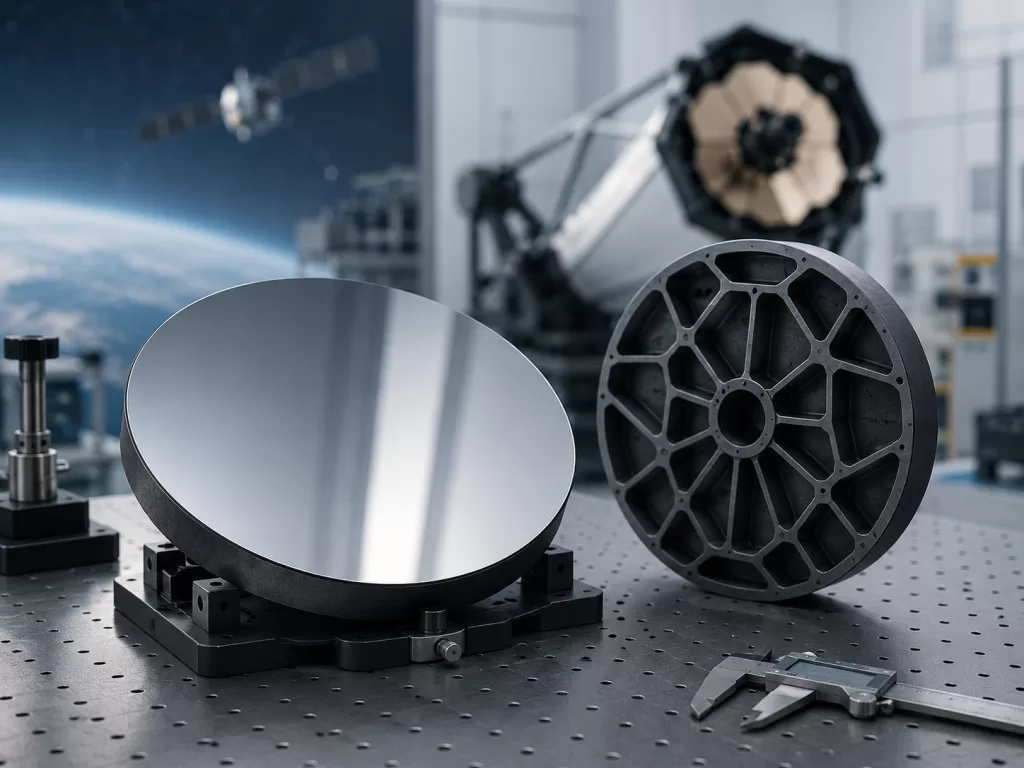
Silicon carbide (SiC) has become an important mirror substrate material for space telescopes, remote-sensing instruments, laser systems, precision metrology, and other optical systems where low mass, high stiffness, dimensional stability, and thermal performance must be achieved simultaneously.
Unlike conventional optical glass mirrors, a SiC mirror can be designed as both an optical surface and a lightweight structural component. This makes silicon carbide particularly attractive for large apertures, fast scanning systems, cryogenic instruments, and optical assemblies exposed to significant temperature changes.
SiC has already been used in major space optical systems. ESA has employed silicon carbide technology in missions including Herschel and Gaia, demonstrating its suitability for large and lightweight spaceborne optical structures.
However, manufacturing a precision SiC mirror involves much more than machining a piece of silicon carbide into a reflective shape. Material grade, lightweighting geometry, substrate fabrication, grinding, polishing, surface figure, roughness, coating design, mounting interfaces, and environmental testing all influence final optical performance.
This guide explains the major considerations engineers and optical-system buyers should evaluate when specifying custom silicon carbide mirrors.
Why Use Silicon Carbide for Optical Mirrors?
A precision mirror substrate must maintain its shape under mechanical, gravitational, thermal, and mounting loads.
For space and high-performance optical applications, designers generally seek a combination of:
- High structural stiffness
- Low mass
- Low thermal expansion
- Good thermal conductivity
- Dimensional stability
- High mechanical strength
- Compatibility with precision optical finishing
- Ability to manufacture lightweight structures
Silicon carbide is attractive because it combines high stiffness, relatively low thermal expansion, and good thermal conductivity. ESA has specifically identified this combination as advantageous for spaceborne optomechanical instruments.
This combination can help an optical system reach thermal equilibrium more rapidly while limiting thermally induced distortion.
SiC Mirrors in Space Applications
Space optical systems operate under conditions that can be difficult for conventional structures.
A mirror may experience:
- Launch vibration
- Mechanical shock
- Large temperature changes
- Vacuum
- Long-term dimensional stability requirements
- Strict spacecraft mass limits
- Limited opportunities for adjustment after launch
Reducing mirror mass while retaining high stiffness is therefore a major design objective.
Silicon carbide has been used in space telescope structures partly because large, stiff optical components can be produced without the mass associated with a completely solid substrate.
ESA’s Herschel telescope used a 3.5 m silicon carbide primary mirror, demonstrating how SiC can support very large spaceborne optical structures.
ESA has also described SiC mirrors undergoing thermal-vacuum qualification to reproduce the temperature and vacuum environments encountered in orbit.
Applications Beyond Space Telescopes
Although space telescopes are one of the best-known applications, silicon carbide mirrors can also be considered for other demanding optical systems.
Typical applications include:
Earth Observation and Remote Sensing
Lightweight mirrors can be used in imaging systems where structural stability and low spacecraft mass are critical.
Laser Beam Steering
Fast-moving mirrors benefit from reduced inertia.
A lighter mirror can potentially support faster acceleration and more responsive beam-control systems, provided sufficient stiffness is maintained.
High-Energy Laser Systems
Thermal stability becomes increasingly important when optical components absorb a portion of incident laser energy.
SiC’s thermal properties can therefore be advantageous in certain high-energy optical systems.
Precision Metrology
Stable mirror substrates may be used in interferometric and high-precision measurement systems.
Synchrotron and Specialized Scientific Optics
CVD silicon carbide has historically been investigated for extremely smooth reflective surfaces used in demanding scientific optical applications. NASA optical-development work has also reported ultrasmooth CVD SiC components for specialized ultraviolet instruments.
Cryogenic Optical Systems
Material stability across wide temperature ranges makes SiC attractive for optical instruments operating far below room temperature.
Solid vs Lightweight SiC Mirror Design
A small precision mirror may be manufactured as a relatively simple solid substrate.
For larger mirrors, however, a solid SiC blank can add unnecessary mass.
The common solution is lightweighting.
Instead of removing material uniformly, the rear structure of the mirror is engineered to remove non-critical mass while retaining sufficient stiffness to support the optical face sheet.
Lightweight Rib Structures
A lightweight SiC mirror may contain:
- Triangular ribs
- Hexagonal cells
- Honeycomb structures
- Radial ribs
- Orthogonal ribs
- Pocketed back structures
- Custom topology-optimized structures
The exact geometry depends on:
- Mirror diameter
- Mirror thickness
- Optical surface shape
- Mounting method
- Allowable deformation
- Acceleration loads
- Thermal conditions
- Target mass reduction
The objective is not simply to make the mirror as light as possible.
Removing too much material can reduce stiffness and make the optical surface more sensitive to mounting forces, gravity, vibration, and thermal gradients.
Lightweighting Ratio
Optical engineers may specify the percentage of material removed or a target final mass.
However, lightweighting should normally be evaluated together with finite-element analysis.
The design should consider deformation caused by:
- Gravity
- Launch acceleration
- Mirror mounting
- Temperature gradients
- Polishing pressure
- Coating stress
A lightweight structure that performs well during normal operation may behave differently during optical fabrication or launch.
NASA development work on lightweight SiC optics has specifically focused on near-net-shape fabrication as a way to reduce the machining needed before optical surfacing.
Face Sheet Thickness
The optical face sheet is especially important.
If it is too thin, pressure from polishing or mounting may create local deformation corresponding to the lightweight cell structure underneath.
This can produce unwanted surface features sometimes associated with print-through.
If the face sheet is excessively thick, however, much of the lightweighting benefit is lost.
The designer therefore needs to balance:
Optical stability + structural stiffness + manufacturing feasibility + weight reduction.
Types of Silicon Carbide Used for Mirrors
“Silicon carbide mirror” does not describe one single material.
Several SiC manufacturing routes can be used, and their microstructures can affect machining and optical finishing.
Reaction-Bonded Silicon Carbide
Reaction-bonded SiC can be used to manufacture relatively large and complex structures.
Advantages may include:
- Large component capability
- Complex near-net shapes
- High stiffness
- Good thermal properties
- Lightweight structural designs
However, the presence of different material phases can affect direct polishing behavior.
For very demanding optical surfaces, an additional surface layer may therefore be used.
Sintered Silicon Carbide
Sintered SiC provides a high SiC content and strong mechanical and thermal properties.
It can be used for precision structural and optical components when the fabrication route and finishing process are appropriately controlled.
CVD Silicon Carbide
Chemical vapor deposited silicon carbide offers a very uniform and high-purity surface material.
CVD SiC can be used as:
- A standalone optical substrate in certain applications
- An optical-facing layer deposited onto another SiC substrate
The second approach combines the structural advantages of a lightweight SiC body with a more uniform surface suitable for precision finishing.
Optical research has demonstrated extremely smooth polished CVD SiC surfaces, illustrating the material’s suitability for demanding optical finishing.
Why SiC Mirror Polishing Is Difficult
The properties that make silicon carbide mechanically attractive also make it difficult to process.
SiC is extremely hard and brittle.
Conventional optical glass can be ground and polished using mature processes, whereas silicon carbide generally requires diamond grinding and specialized finishing techniques.
Research on SiC optical fabrication shows that grinding behavior, subsurface damage, and material grade all influence the final surface and subsequent polishing requirements.
A typical SiC mirror manufacturing route may therefore include several stages.
1. Near-Net-Shape Fabrication
The substrate is first manufactured relatively close to its final geometry.
At this stage, the major structural features may already be present:
- Mirror curvature
- Rear lightweight pockets
- Ribs
- Mounting bosses
- Central holes
- Interface features
Reducing unnecessary material before precision machining can lower later grinding requirements.
2. Precision Grinding
Diamond grinding is used to establish the mirror geometry.
Grinding may control:
- Diameter
- Optical curvature
- Thickness
- Mounting interfaces
- Preliminary surface figure
The process typically moves from coarse material removal toward progressively finer finishing.
Poor grinding control can introduce:
- Subsurface damage
- Microcracks
- Edge chipping
- Surface irregularity
- Excessive material for later polishing
Optimized grinding strategies can greatly improve the surface before final optical finishing. Studies of reaction-bonded SiC have demonstrated that carefully controlled ductile-mode grinding can significantly improve surface roughness compared with conventional brittle removal.
3. Fine Grinding and Damage Reduction
Fine grinding reduces the damage created during earlier machining stages.
This is particularly important because microscopic cracks below the surface can affect both optical fabrication and mechanical reliability.
A visually smooth surface is not necessarily free of subsurface damage.
Therefore, process development may evaluate both:
Surface roughness
and
subsurface damage depth.
4. Optical Polishing
The final polishing stage must control two fundamentally different characteristics.
Surface Figure
Surface figure describes how closely the finished mirror matches its designed optical geometry.
For example:
- Flat
- Spherical
- Parabolic
- Hyperbolic
- Aspheric
- Freeform
Surface Roughness
Surface roughness describes microscopic surface texture.
A mirror can have excellent figure but poor roughness, or excellent roughness but incorrect overall figure.
Both must be specified independently.
Polishing Technologies for SiC Mirrors
Depending on material grade and optical requirements, processing may involve combinations of:
- Conventional optical polishing
- Diamond-based polishing
- Computer-controlled optical surfacing
- Magnetorheological finishing
- Ion-beam figuring
- Chemical-mechanical finishing
- Other deterministic finishing processes
Magnetorheological finishing and computer-controlled optical surfacing have been demonstrated for precision SiC optical surfaces and can be used to improve surface figure and control polishing errors.
No single polishing route is optimal for every mirror.
Process selection depends on:
- Mirror size
- SiC grade
- Surface coating or cladding
- Initial figure
- Required roughness
- Required wavefront performance
- Production volume
- Budget
Surface Figure Requirements
The correct optical specification depends heavily on wavelength and system architecture.
Common specifications can include:
- Surface figure error
- Peak-to-valley error
- RMS surface error
- Power
- Irregularity
- Zernike coefficients
- Local slope error
For precision mirrors, simply stating:
“Optical quality surface”
is usually insufficient.
The drawing should define measurable acceptance criteria.
Surface Roughness Requirements
Surface roughness influences scattering and can be especially important at shorter wavelengths.
Specification methods may include:
- Ra
- RMS roughness
- PSD-based surface characterization
The required roughness should be selected according to the operating wavelength and optical performance target.
An infrared mirror and a mirror intended for much shorter wavelengths may require very different surface-finish specifications.
Applying an unnecessarily strict surface requirement can significantly increase manufacturing time and cost.
Mid-Spatial-Frequency Errors
Surface quality is not determined only by overall figure and microscopic roughness.
Between these scales are mid-spatial-frequency errors.
These errors can be introduced by:
- Grinding
- Tool paths
- Sub-aperture polishing
- Deterministic finishing
They may influence stray light, contrast, and image quality.
Modern SiC optical fabrication research therefore increasingly evaluates not only PV and RMS figure but also spatial-frequency-dependent surface errors.
For demanding imaging systems, buyers should consider whether PSD or mid-spatial-frequency specifications are required.
Edge and Clear Aperture Requirements
The optical surface normally includes an active region known as the clear aperture.
The drawing should distinguish between:
- Overall mirror diameter
- Clear aperture
- Edge exclusion
- Chamfer or bevel
- Mounting area
The very edge of the mirror is generally more difficult to polish and measure accurately.
Defining a realistic edge exclusion can reduce unnecessary manufacturing difficulty.
Aspheric SiC Mirrors
One major advantage of modern precision manufacturing is the ability to produce SiC mirrors with non-spherical optical surfaces.
Possible geometries include:
- Parabolic mirrors
- Hyperbolic mirrors
- Elliptical mirrors
- Off-axis parabolic mirrors
- Freeform mirrors
These surfaces may reduce the number of optical elements required in a system.
However, manufacturing and metrology become more complex as the surface departs further from a simple sphere.
The RFQ should therefore include the complete mathematical surface definition or 3D optical model.
SiC Mirror Coatings
After polishing, most SiC mirrors require a reflective coating appropriate for their operating wavelength.
The substrate provides the structural and thermal foundation.
The coating provides the required optical response.
Common reflective coating families used in optical systems can include:
- Aluminum-based coatings
- Silver-based coatings
- Gold-based coatings
- Dielectric multilayer coatings
- Specialized UV or infrared coatings
The correct coating depends primarily on the wavelength range and operating environment.
Aluminum Coatings
Aluminum is widely used for broadband reflective optics.
Depending on the application, a protective or enhanced layer may be added to improve durability or optical performance.
The exact coating stack should be selected according to the required spectral range.
Silver Coatings
Silver can provide high reflectivity across important visible and infrared regions.
However, environmental protection is important because an unprotected metallic surface may degrade under certain exposure conditions.
Protected or enhanced silver systems are therefore often considered.
Gold Coatings
Gold is frequently considered for infrared optical systems.
It is particularly useful when high infrared reflectivity is required and visible-light performance is not the primary concern.
Dielectric Coatings
Dielectric multilayer coatings can be designed for specific wavelengths or wavelength bands.
Possible objectives include:
- Very high reflectivity
- Narrow-band operation
- Laser-line reflection
- Spectral filtering
- Environmental protection
The tradeoff is that coating performance may become more wavelength- and angle-dependent.
Coating Stress
Applying a coating does not simply change reflectivity.
Thin-film stress can slightly deform an optical substrate.
This effect becomes particularly important for:
- Large mirrors
- Thin face sheets
- Lightweight mirrors
- Extremely tight surface-figure tolerances
The optical engineer should therefore consider the complete system:
substrate + lightweight structure + polishing + coating + mounting.
Final optical verification after coating may be required for demanding systems.
Mirror Mounting Interfaces
An excellent optical surface can still perform poorly if the mirror is mounted incorrectly.
Mounting forces can deform the substrate.
Possible mirror interface designs include:
- Three-point mounts
- Flexures
- Integrated mounting bosses
- Bonded interfaces
- Kinematic supports
- Custom lightweight structures
Mount design should account for:
- Mechanical preload
- Thermal expansion mismatch
- Gravity orientation
- Vibration
- Launch loads
- Temperature variation
Whenever possible, optical and mechanical design should be developed together rather than treating the mirror mounting system as a secondary issue.
Inspection and Metrology
A custom precision SiC mirror may require several different inspections.
Dimensional Inspection
This can include:
- Diameter
- Thickness
- Mounting-hole location
- Interface dimensions
- Lightweight structure dimensions
Surface Figure Measurement
Interferometry is commonly used for precision optical verification where the geometry allows.
Measurements may be performed at specific wavelengths and under defined mounting conditions.
Surface Roughness Measurement
Possible techniques include:
- Optical profilometry
- Interferometric microscopy
- Atomic force microscopy for specialized applications
Coating Inspection
Depending on requirements, coating verification may include:
- Reflectivity
- Transmission where relevant
- Spectral performance
- Adhesion
- Environmental durability
- Visual surface inspection
Environmental Qualification
Space and other demanding optical systems may require more than room-temperature optical inspection.
Qualification may include:
- Thermal cycling
- Thermal-vacuum testing
- Vibration
- Mechanical shock
- Humidity testing
- Coating durability testing
ESA has publicly demonstrated thermal-vacuum testing of silicon carbide mirror structures intended to reproduce orbital environments.
Qualification requirements should be defined before manufacturing because they can affect material selection, bonding, coating, mounting, and inspection planning.
Common SiC Mirror Manufacturing Challenges
Typical problems include:
Edge Chipping
SiC is brittle and can chip during machining or handling.
Subsurface Damage
Grinding may leave microscopic cracks beneath the surface.
Polishing Print-Through
A thin face sheet or aggressive lightweight structure can contribute to periodic surface deformation.
Surface Figure Errors
Grinding and polishing processes may leave low- or mid-spatial-frequency errors.
Coating-Induced Distortion
Coating stress may alter the finished optical figure.
Mounting Deformation
Improper support or excessive preload can distort the mirror.
Thermal Distortion
Temperature gradients can change mirror shape even when the substrate itself has favorable thermal properties.
These issues should therefore be evaluated as part of a complete optical manufacturing process rather than as independent problems.
What Information Should Be Included in a SiC Mirror RFQ?
A detailed RFQ helps an optical manufacturer evaluate feasibility and provide a more accurate quotation.
1. Mirror Geometry
Provide:
- Diameter
- Thickness
- Overall dimensions
- Central hole if required
- Mounting interfaces
- Lightweight structure
A 3D CAD model is strongly recommended for complex lightweight mirrors.
2. Optical Surface Type
Specify:
- Flat
- Spherical
- Parabolic
- Hyperbolic
- Off-axis
- Aspheric
- Freeform
For aspheric surfaces, provide the complete optical prescription.
3. SiC Material
Indicate whether a specific material is required, such as:
- Reaction-bonded SiC
- Sintered SiC
- CVD SiC
- SiC substrate with an optical-facing layer
If the material has not yet been selected, provide the operating conditions and allow the manufacturer to evaluate suitable options.
4. Surface Figure
Specify measurable requirements such as:
- RMS
- PV
- Power
- Irregularity
- Slope error
Include the measurement wavelength where relevant.
5. Surface Roughness
Define the required roughness and measurement method.
6. Clear Aperture
Clearly define:
- Clear aperture diameter
- Edge exclusion
- Non-optical regions
7. Coating
Provide:
- Operating wavelength
- Required reflectivity
- Angle of incidence
- Polarization if relevant
- Environmental conditions
Avoid specifying only:
“AR coating” or “high-reflection coating.”
The spectral requirement is much more useful.
8. Lightweighting Requirement
Specify:
- Maximum mirror mass
- Lightweighting target
- Structural design if predetermined
- Allowable deformation
- Mechanical-load requirements
9. Mounting Interface
Provide complete dimensions and tolerances for:
- Holes
- Bosses
- Threads
- Bonding surfaces
- Datum surfaces
10. Operating Environment
Include:
- Operating temperature
- Temperature range
- Vacuum conditions
- Vibration requirements
- Mechanical acceleration
- Radiation environment if applicable
11. Inspection Requirements
Specify whether you require:
- Dimensional report
- Interferometric report
- Surface roughness report
- Coating spectral report
- Material certificate
- Environmental test report
12. Quantity
State whether the requirement is for:
- Prototype
- Engineering qualification unit
- Flight unit
- Research system
- Production quantity
Example SiC Mirror RFQ
A basic enquiry might contain the following information:
Product: Lightweight Silicon Carbide Mirror
Application: Precision remote-sensing optical system
Mirror diameter: 300 mm
Optical surface: Concave asphere
Material: SiC, supplier recommendation accepted
Lightweight structure: Rear rib structure
Clear aperture: According to drawing
Surface figure: According to optical specification
Surface roughness: According to wavelength requirement
Coating: High-reflectivity coating for specified wavelength band
Mounting: Three integrated mounting interfaces
Environment: Vacuum and thermal cycling
Quantity: 2 prototype mirrors
Inspection: Dimensional, interferometric, roughness and coating reports
Providing the optical drawing and 3D structural model together is usually much more effective than sending only a mirror diameter and focal length.
Choosing a Silicon Carbide Mirror Manufacturer
A supplier for precision SiC optics should be evaluated differently from a supplier manufacturing ordinary SiC ceramic parts.
Important capabilities may include:
- SiC material manufacturing
- Near-net-shape forming
- Lightweight structure fabrication
- Diamond machining
- Precision grinding
- Optical polishing
- Deterministic finishing
- Interferometric measurement
- Surface roughness measurement
- Optical coating coordination
- Mechanical and environmental qualification
Large or high-precision SiC mirrors often require close cooperation between material engineers, structural designers, optical fabricators, coating suppliers, and metrology teams.
Early design-for-manufacturing discussions can therefore reduce technical risk and unnecessary cost.
Conclusion
Silicon carbide mirrors offer an attractive combination of low mass, high stiffness, thermal stability, and structural performance for demanding optical systems.
These characteristics have made SiC particularly important in space telescopes and remote-sensing instruments, while also creating opportunities in laser systems, precision metrology, scientific instrumentation, cryogenic optics, and other high-performance applications.
However, manufacturing a precision SiC mirror requires careful control of the complete process chain:
material selection → lightweight structure → machining → grinding → polishing → optical metrology → coating → mounting → environmental qualification.
For buyers, the most important step is to define functional requirements rather than simply requesting a “high-precision SiC mirror.”
A complete RFQ should include the mirror geometry, SiC material, optical prescription, clear aperture, surface figure, surface roughness, coating wavelength, mounting interfaces, lightweighting requirements, operating environment, inspection criteria, and quantity.
When these parameters are defined early, the mirror substrate, optical finishing process, coating system, and mechanical structure can be optimized together for better optical performance and manufacturing reliability.
FAQ
Why is silicon carbide used for space mirrors?
Silicon carbide combines high stiffness, relatively low mass, low thermal expansion, and good thermal conductivity. These properties make it attractive for lightweight optical structures that must maintain dimensional stability during launch and temperature changes.
Can silicon carbide be polished to optical quality?
Yes. SiC can be processed to precision optical surfaces using specialized grinding and polishing techniques. Depending on the SiC grade and performance requirements, processes may include fine grinding, computer-controlled polishing, magnetorheological finishing, and other deterministic finishing methods.
Why are SiC mirrors lightweighted?
Removing non-critical material from the rear of the mirror reduces mass while a carefully designed rib structure retains structural stiffness. This is especially valuable for spacecraft and fast-moving optical systems.
Can reaction-bonded SiC be used for precision mirrors?
Yes, but the material microstructure and optical requirements must be considered. In demanding applications, an additional optical-facing layer or specialized finishing process may be used to obtain the required surface.
What coating should be used on a SiC mirror?
The coating should be selected according to operating wavelength, required reflectivity, angle of incidence, polarization, environmental conditions, and durability requirements. The SiC substrate itself does not determine the final reflective coating.
What should I provide when requesting a custom SiC mirror?
Provide the optical drawing, 3D model, mirror dimensions, optical surface prescription, SiC material requirements, surface figure, surface roughness, clear aperture, coating wavelength, mounting design, environmental conditions, inspection requirements, and quantity.